Project Software Engineering
Improving the design flow
Project - M1 - Software Engineering
We want to improve the current engineering flow for producing protection masks used by the medical staff. The masks are 3D shapes. We have two different production flows :
- One with 3D printing
- One with Laser cut (2D projection)
Current Flow
Tools
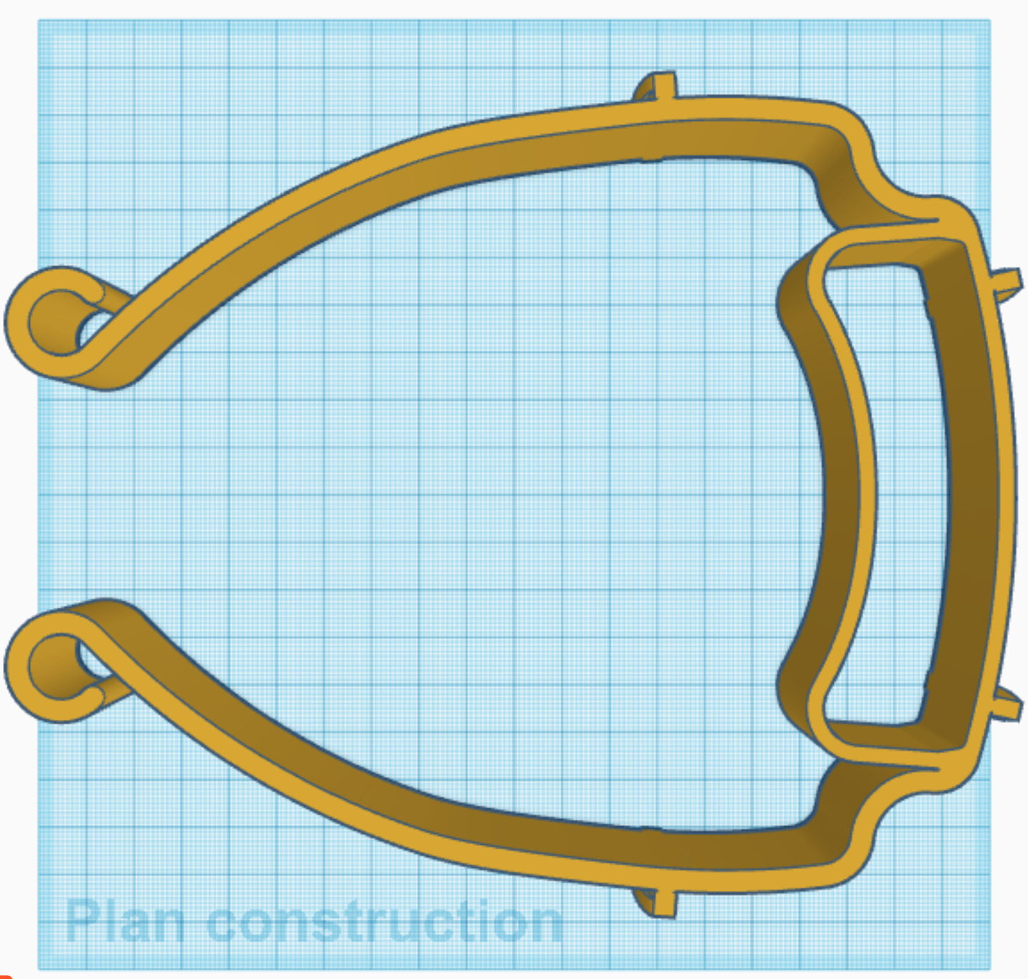
- Shapes are created in 3D using : simple Meshes, constructive solid geometry (CSG) or boundary representation (BRep) using tools like TinkerCAD or FreeCAD and stored as .STL files. See section 3D Printing below. STL files can be directly imported into 3D Printing tools like Cura and sent to the 3D printer. Theses shapes are either built using tools or generated using Javascript shape generators (in TinkerCAD, for instance) or Python scripts (using FreeCAD library, for instance).
- 3D shapes are flattened into 2D Paths as SVG files. SVG paths can be modified and adapt using tools like Inkscape or GIMP.
- Once modified, the 2D paths are exported as DXF files to be used by tools for laser cutting.
- DXF files are imported and handled using proprietary tools like RDWorks to be annotated and send to the laser cutter. See section Laser cut below.
This is a bad flow since STL store shapes as set of triangle faces, reconstructing paths from faces is error-prone while the STL shapes are initially generated from paths. So we want to change the flow (see new flow).
3D Printing
The tool for 3D printers starts with .STL files. The 3D shapes are sliced into 2D layers, a path in 2D of a given thickness. STL files mainly contain meshes, here we consider, as a first approximation, a list of points (in 3D) and a list of faces (mainly triangles : list of 3 points, but could be other shapes).
Laser cut
Shapes
The tool for cutting 2D shapes uses gcode, a list of moving instructions following a specific 2D path. We can use several 2D layers to build a complex 3D shape. The simple case uses a single 2D layer.
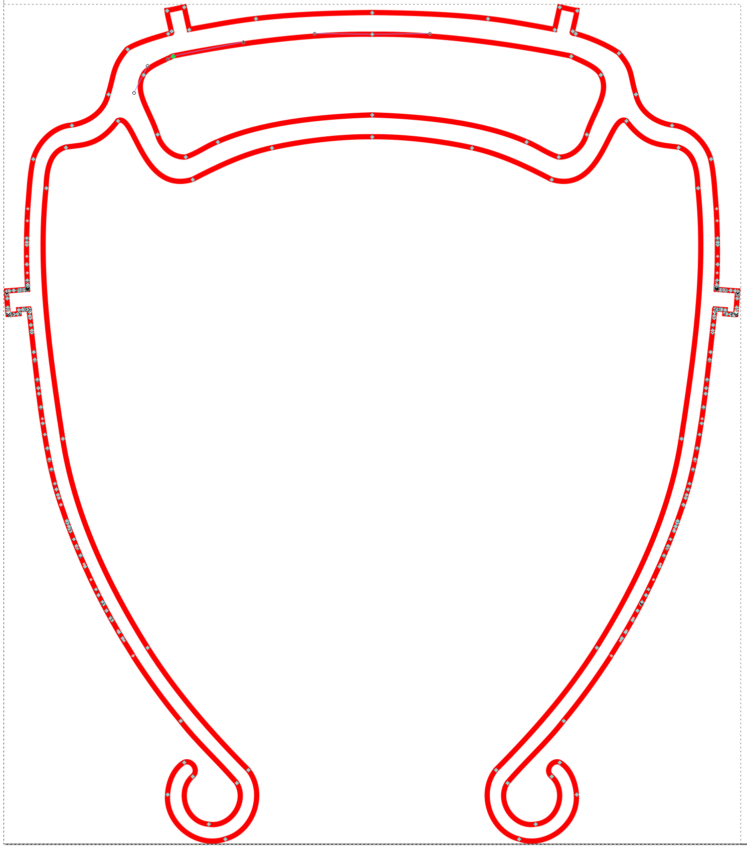
One 2D layer is a set of 2D paths, a sequence of 2D points or a group of 2D paths. The figure below gives an example of SVG path. Points can be linked by simple lines or by Bezier curves.
Tiling and paving of shapes
Each shape can be replicated several times to optimize the use of raw material (e.g., Plexiglass) used in the process. To replicate shapes, we can :
- either make an ordered list of shapes ;
- or use a repetitive tiling and paving pattern that replicate shapes into meshes of shapes. For instance 2DMESH(mask, 4,10 mm, 2, 5 mm) will make a new shape that replicates the shape mask over a regular 2D mesh, where the basic shape (e.g., mask) is duplicated 4 times horizontally and 2 times vertically, separating the horizontal replicates by a distance of 10 mm and the vertical replicates by a distance of 5 mm.
The figure below gives an example of list of Parameterized shapes (see the dashed paths). This list is a mix of absolute position shapes and tiled shapes. In the top part of the figure, the basic shape is made of two masks and is replicated 3 times horizontally and 1 time vertically, with a negative distance between the horizontal replicates. In the bottom part of the figure, the basic shape is replicated twice horizontally and once vertically with a positive distance between the consecutive horizontal replicates.
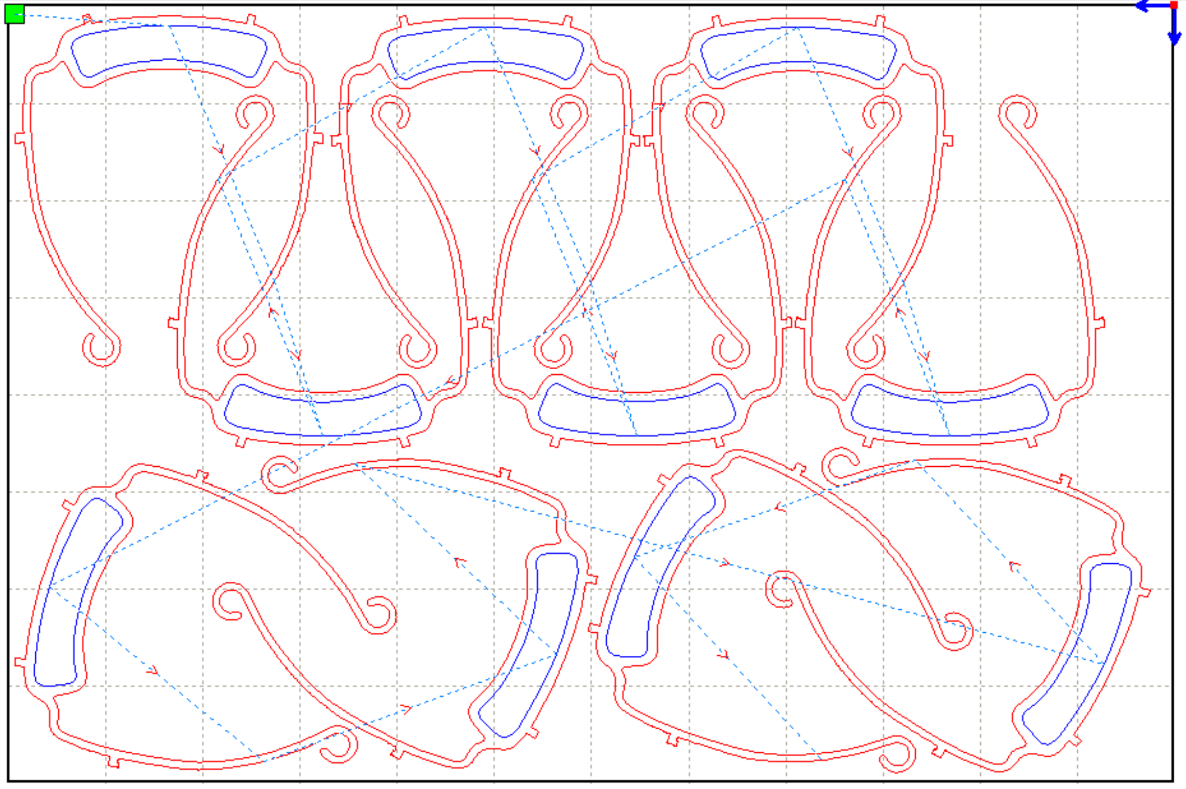
On the figure above, we can see that the shapes are associated to layers. Each layer has a different color (here red and blue) that represents a different configuration.
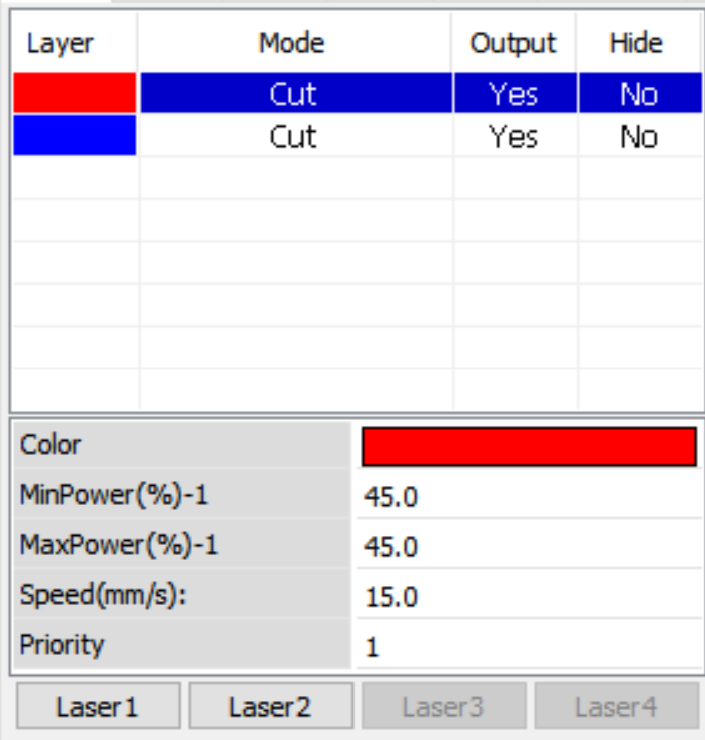
A Configuration for a layer contains a minimal and maximal laser power as well as a moving speed:
- The laser power is expressed as a percentage of the maximal power that the laser can produce. Here the minimal and maximal laser power for the red shapes is 45%.
- The moving speed is expressed in mm/s (here the red shape cuts at 15 mm/s).
All these cutting instructions are sent to the laser cutter as a sequence of GCODE instructions.
The table below gives an example of powers depending on the colors. We can see that the configuration also contains the output parameter (yes or no) that says that the layer is used or ignored. When Output is no, the layer is not cut. When Output is yes, the layer is cut.
New flow
In the new flow, we would like to have a repository of models as inputs and generate the different files using the different concrete syntaxes as needed. Potentially, we want to use use existing tools to modify and convert some of the formats and then be able to import some shapes from some of the file formats.
To do that, the first step is to create a meta-model for each model that we want to deal with.
Meta-Models
This section gives a list of the meta-models that we might need in the new flow. You should select at least one input and one output.
Input formats (also outputs)
- Simple Meshes : possibly using replicating patterns (see section Tiling and Paving above) ;
- CSG : constructive solid geometry ;
- BRep : boundary representation.
Output formats
- .STL files : Standard Triangle Language for 3D printing;
- SVG path : with configurations, for laser cutting
- DXF files : with configurations, for laser cutting
- gcode : for laser cutting
- Python FreeCAD scripts : see Lab1 on Python’s metamodel ;
- TinkerCAD Shape Generator Javascript library : similar to Lab1 with Javascript metamodel ;
Assignment
- Task 1: Select (at least) one input and one output and propose a meta-model for it
- Task 2: Propose a SWITCH visitor to produce the output in the official concrete syntax (you can also produce a pretty printer for helping the debug process).
- Task 3: Propose a Native Visitor to produce the output in the official concrete syntax. This task has a very big overlap with the previous task.
- Task 4: Propose an XText Parser for the input format that you have selected
- Task 5: Propose a Sirius Editor for the input format that you have selected
- Task 6: Propose a transformer to transform the input selected into the output selected. You must use the input to go into your internal model (this is what you have to do anyway for tasks 4 and 5) and then produce the output from the internal formal (using Task 2 or Task 3).
DIVERS
NEWS Fablab